Goto USPTO Information Page for this patent
#173,177
2/8/1876 - Josef Nicht of Auburn N.Y. "Improvment in Bench Planes" (lateral adjustment)
UNITED STATES PATENT
OFFICE.
|
||
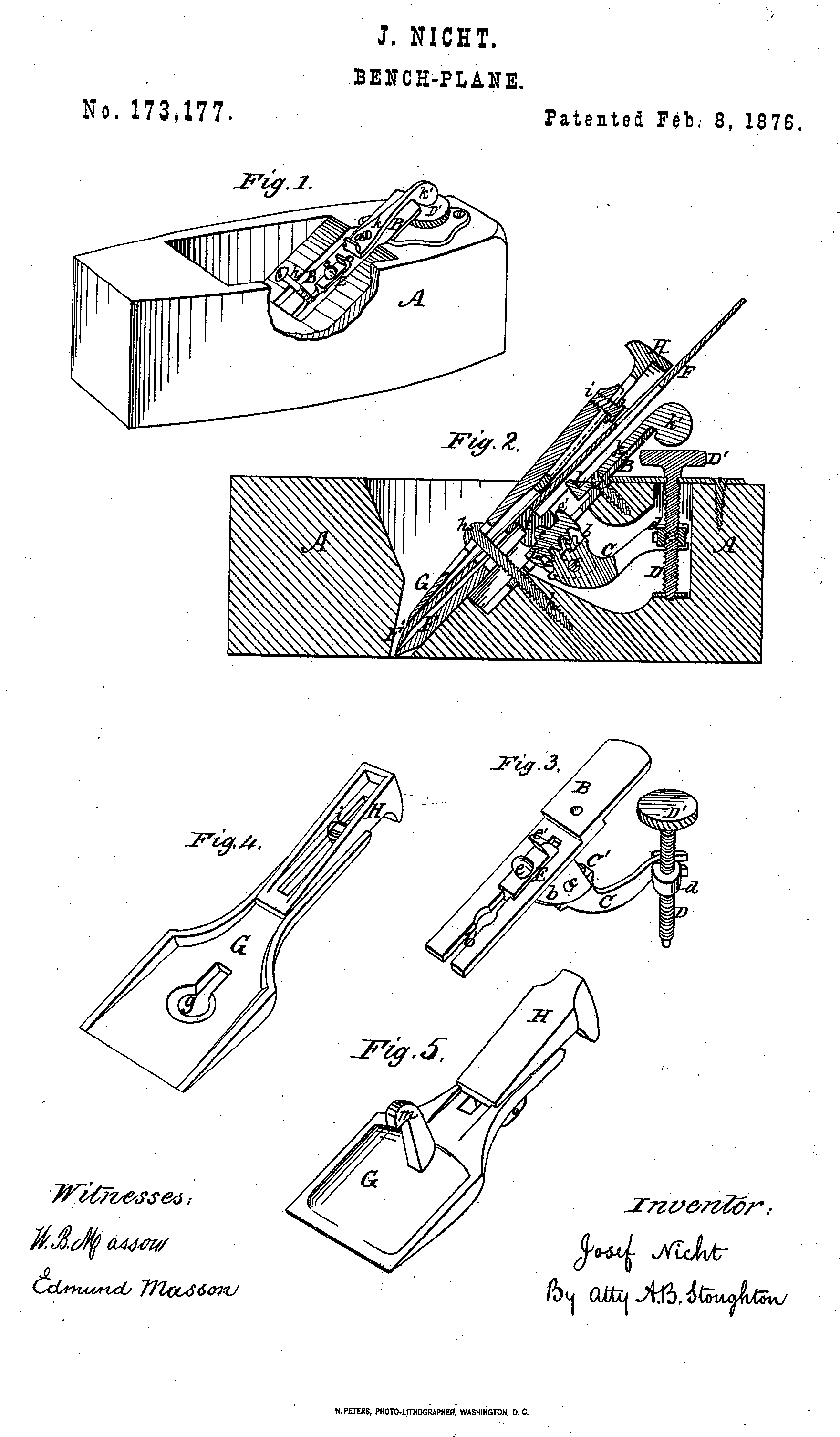
| To all whom it may concern: Be it known that I, JOSEF KICHT, of Auburn, in the county of Oayng-a and State of New York, have invented certain new and useful Improvements in Bench-Planes; and that the following is a full, clear, and exact description of the same, reference being had to the accompanying drawings making a part of this specification, in which— Figure I represents a perspective view of my improved plane, with the 'plane-irons and fastening-cap 'removed. Fig. 2 represents a longitudinal vertical section, through my im- proved plane. Fig. 3 represents a detached view of the mechanism employed for raising or lowering the plane-irons. Fig. 4 repre- sents a perspective view of the cap overlying the plane-irons, showing its under side 'and connected wedge. Fig. 5 represents a modi- fication of the same. Similar letters of reference, where they oc- cur, denote like parts' in all the figures. My invention relates to certain combina- tions of mechanisms used to set or adjust plane-irons from the exterior of the plane with- out separating the parts, and with great ex- pedition and accuracy. My invention relates also to the means by •which the plane-irons can be moved laterally to adjust them in that direction, and also to the means by which the plane-irons are retained in position by means of a cap and wedge. To enable others skilled in the art to make and use my invention, I will proceed to de- scribe the same with reference to the draw- ings. A represents the wooden stock of a plane, to which is attached, by means of the screw a, the plate B, that has formed on its under side bearings b for the shaft c, around which the geared segment and lever C revolve. The rear end of this lever C is slotted, so as to fit over a pin formed on one side of the nut d, that is raised or lowered by a screw- shaft, ~D, having a knob or thumb-piece, D', upon its upper end, by which it may be read- ily operated to raise or lower the nut <?, and correspondingly the rear end of the lever 0. On the front of the lever C there is a geared segment, C', that engages with the rack B. This rack is located in a groove, V, cut out of the plate B, so as to furnish it with the bearings required for a free and steady mo- |
tion up or down. This rack B has on its up' per surface a
central projection, e, and an- other at e', either or both of which engage with the head
of a screw,/, that is centrally recessed for that purpose. This screw / is otherwise the
one employed to connect the plane-iron F and its iron cap ~F', so that by turning the
screw-shaft D the plane-irons inay be moved np or down at pleasure to ad- just them, and
when adjusted they are firmly held in that position. G is a metallic cap overlying the
plane - irons. A slot, g, is cufc through it, so as to allow the head of the screw h to
pass through it and rest on its upper surface. TTnder the rear of this cap G- there is a
wedge, H, by which the cap may be raised at that point and pressed against the plane-irons
at or near their lower ends to clamp them together. The wedge H is retained in connection
with the cap & by grooves formed on the latter, and a bolt, i, that connects the two
together. To the plate Baud stock A is pivoted at a a lever, 1c, the rear end of which
projects upward, so as to be readily operated from the exterior of the plane, it
terminating in a knob, 1c', by which it can be moved. The inner end of this lever 1c is
bent up, as at I, and passes into the slot ordinarily cufc in plane-irons -F, so that the
latter can be moved laterally to adjust said irons in that direction. Thus the vertical
and lateral adjustments of the plane-irons maybe instantly and very accurately made. In Fig. 5 is shown a modification of the cap G, the slot g of Fig. 4 being dispensed with, and the book m formed in its place, so as to engage under the head of a bolt, or any simi- lar projection attached to the stock A of the plane. .. I claim as my invention- In combination with the plane-stock A, the longitudinally-slotted plane-iron F and the mechanism composed of the screw Ji and cap G-, carrying, secured to it, the wedge H, for clamping said plane-iron to' the plane, the lever 1c', pivoted to the stock of the plane, and engaging with the slot of the plane-iron to adjust it laterally, all arranged substan- tially as shown and described. JOSEF NICHT, Witnesses: HORACE T. COOK, W. P. BEARDSLEY. |
|