Goto USPTO Information Page for this patent
#1,918,750 Earl V. Higbee's 7/18/1933 (lever cap)
| Patented July 18,1933 1,918,750 UNITED STATES PATENT OFFICE BAKL V. HIGBEE, W ITEW BErTA:i::r.r, GOK•ITECTIC•0•T,ASSIQ•M'OE• 'TO THE STANlEY •WORKS, OF NEW BRITAIN, COH'JJSGTICtrT, ACOEPOHATION OF CONNECTICU1C - , • • '~ FIAITE • ~ -" . . • • ApplicatioiifilcdJTilyl8,193a.SeriallTo.623,159. |
||
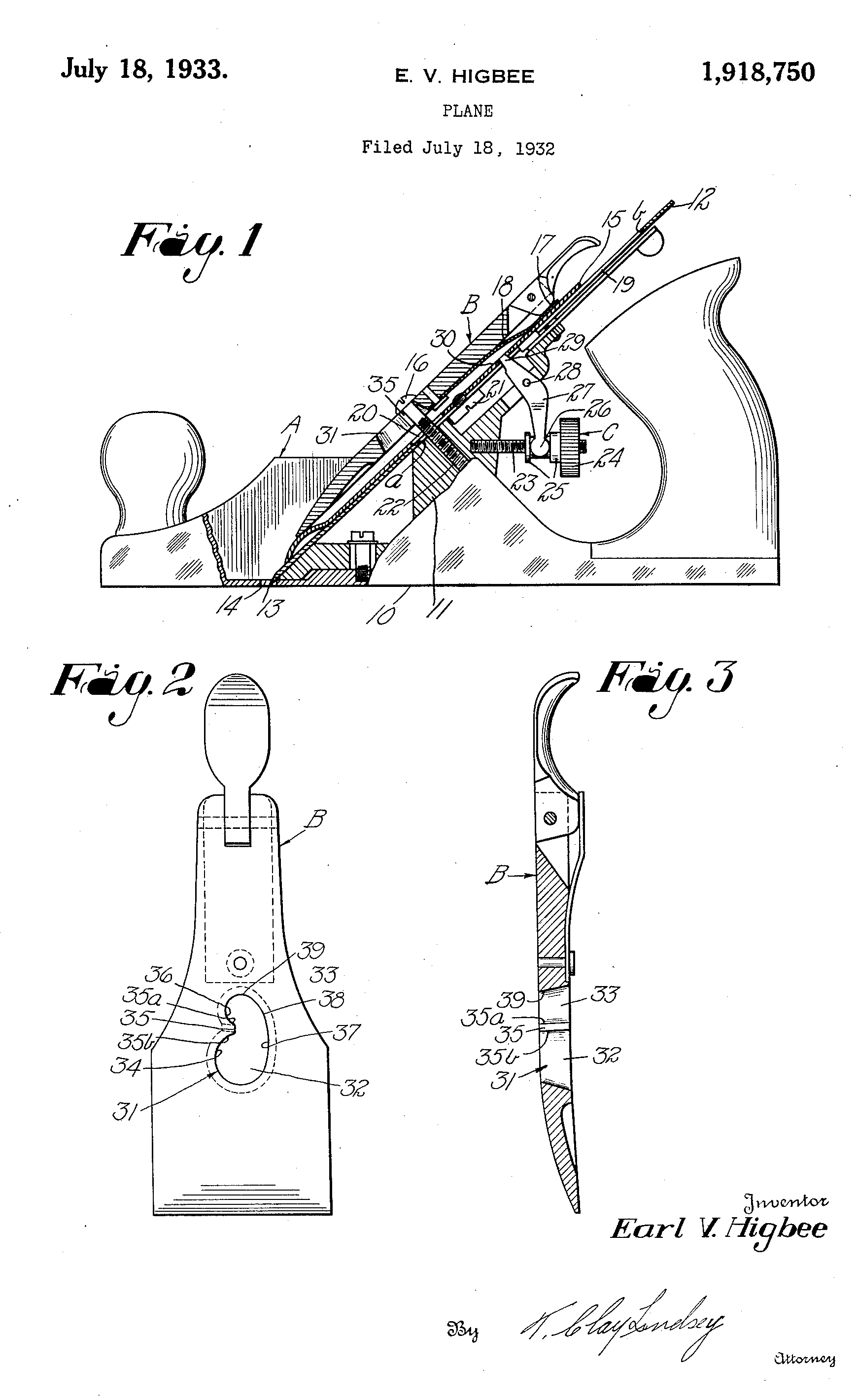
| The present invention relates to planes such as disclosed in the Patent No. 1,812,820, granted June 30, 1931, to James M.Burdick. In planes of this character, when the cutter 5 is constantly adjusted .forwa-i'dly and b~~lr--- wai-dly,th.eclamping'levei' tends to move back and loosen on the lever screw. It is an object of the present invention to provide an .improved clamping lever for 1!) planes of this kind which will overcome to a very large degree, if not entirely, the above noted objection. It is another object of the present inven- tion to provide an improved clamping-lever 1.1 forpla-ncs of this cha,racter which possesses a greater, holding power than the old style lever. A further object of the -present invention is to provide an improved clamping I lever 2() for planes of this cha-racter which requires relatively small alteration of the old style lever but which will obtain the advantageous results pointed, out above. A still further object of the present linven- 25 tion is to provide an improved clamping le- v-er for devices of this character which may be manufactured at .substantially the. same cost as the old style lever. ... • Other objects will be in part obvious, and 30 in part- pointed out more in detail herein- after.- . - - .. The invention accordingly consists in the features ofeonstriiction, combination of ele- ments and arrangement of pa.rts which will ~ be exemplified in the construction herein- after set forth-and the scope of the appli- cation of which will be indicated in the ap- pended claims. In the accompa-nying drawing, wherein is 40 shown, for illustrative purposes, one embod- iment which the present invention may take, Fig. I is a- side view, partly, in section, and partly in elevation, of. a. .plane showing my improved clamping lever applied there- 45 o; Fig. 2 is a front elevation of my improved clamping lever; and Fig. 3 is a longitudinal section of the .same. Referring more particularly to thedraw- so ing, A generally represents a plane of a well known type, and B generally repre.sents my improved clamping lever applied, thereto. The plane A may be of the usual construction and comprises a plane bottom 10 which sup- 55 ports a wedge-shaped block ;member II | against which bears a blade 12 having a cut- ting edge 13 extending through an opening 14 in the plane bottom. 10. A cap plate 15 bears upon the upper surface of the .blade 12 and is clamped thereagainst by the lever B 00 which jsheld in position by a lever screw 16, a cam 17 and a spring 18 of usual construc- tion. The blade 12 is provided wit~ a centrally disposed longitudinally extending slot 19 65 which extends from a. point a rearwardly to a point t> and the cap plate 15 is provided with an opening 20 registering with a lower portion of the slot 19 in the blade 12. The blade 12 and the cap plate 15 are secured to- 70 gether by a screw 21 in the usual manner so that. they move together. The screw 16 passes through the slot 19 and the opening 20 and is received by a screw, threaded socket 22' in the block II. ' . 75 .In order to adjust the bla'debackwardly and-forwardly,aB. adjusthig mechanism, gen- erally. indicated at C, is provided. The mechanism C comprises a screw threaded bar 23 non-rotatably secured- in the block II. A .80 nut 24 is threaded upon the bar 23 and ig pro- vided with a pair of spaced apart collars 25 between which are confined the heads 26 (only one of which is shown) of a lever 27 which is pivoted, as a,t 28, intermediate its 85 ends to the block II. . The. free end 29 of the . lever 27 passes through the slot 19 in the blade 12 and. engages in an opening 30 in the cap plate 15. . The end 29 of the lever 27 en- gages the ends of the opening 30 so that the 00 • cap plate 15 and ;blade .12. are moved for- wardly .or backwardly by the lever 27 de- pendent up on the d.irectio.n of .movement of ! the nut 24 with which the lever is operatively • connected. . . • 05 , The clamping lever B is of substantially i the same construction as the old style lever : with the exception that, instead of the usual • keyhole slot, my improved, clamping lever B is provided with a somewhat kidney-shaped 100 . slot 31. This slot is provided with an en- larged forward portion 32 and arestricted . rearward portion 33 of less. width than the • dia.meter of thehea.dof the screw 16. Be- 1 tween the enlarged portion and the restricted 105 " portion, the wall 34 of the slot 31 is provided . with an inwardly extending projection 35 i whereby an offset 36. is formed at one side, of • the restricted portion 33 of the slot. The L projection 35 is provided with an inwardly 1 10 | |
| and rearwai-dly facing shoulder S5a and with an inwardly andforwardly facing shoulder 35&. The opposite wall 37 of the slot is curved inwardly and rearwardly, as at 38, 5 towards the offset 36 and merges with the rear end wall 39 of the slot. In the use of the device, after the .blade 12 and the cap plate 15 have been properly placed upon the block II, the lever screw 16 is 10 screwed .into the block II, the lever B with the cam IT in a position at substantially right angles to tha.t shown in Fig. I is then placed upon the cap plate by threading the enlarged portion 32 of the slot 31 over the head of the 15 screw 16. The lever Bis now moved down- wardly and forwardly and should the wall. 37 of the slot 31 engage the shank of the screw 16 due to the curvature 3.8 'of the wall 37. the lever B will be. guid.ed by the shank of the 20 screw 16. so that the offset 36 ;of the slot 31 will. be caused to receive the shank of the screw 16. It will be noted, that the shoulder 356 of the projection 35 is curved inwardly and 26 rearwa.rdly so that, in assembling the lever B upon the screw 16, should the shank of the screw become engaged against the shoulder 356. forward, movement of the lever will cam .the same to one side so that the protection 30 35 will clea.r the shank of .the screw a.ndthe curved portion 38 of the wall 37 will engage the shank of the screw and the. lever B will be guided so that the offset 36 will receive the shank of the screw 16. It is thus apparent 9LI that regardless of whether the shoulder 35Z> or the wall. 37 of the slot 31 engages the shank of the screw the lever will be so guided that the offset 36 will be caused to receive the shank of the screw. At this time, the shank of the 40 pcrew 16 will be en.nraared nt its front and rear sides by the shoulder 8Fin and the wall 39 respectively. The cam 17 is then swung to the position shown in Fig. 1. whereupon the rear end of the clamping lever B is moved. 41 outwa.rdlywithresr)ect to the blade 12 to bind. the upper surfaces of fhewalls. of the restricted portion 33 of the slot 31 against the 1iTid.er surface, of the head. of the screw 16. The lever B will now be held positivelv 60 a.ga~nst anv longitudinal movement since the Fhank of the screw 16 is confined between and pn5•?1"•pd bv the SF l~oulrlpT 35(7, and the pnd wnll 39 of the slot. The a.diustin."" means C is. now manipulated to properly adiust the bla.dc12 to the. desirpd position. When thp ncli!lRt- ing-mea,ns Cis ma.nipu.lat~d.to adiustthe blade 12 back, the p,hculder35ffi engaging the front wall of the; screw shank will. prevent the clamping lever B from moving back and loosening on the lever screw 16. Asmanycha,nges could be.made in the above construction and many a.pparently widely different, embodiments of this inven- „, tion could bemad.e without departing from | L the scope thereof, it is intended that all ma.t- • ter contained in th" ab'Oi'c de.sc.1'i.ption 0!- 5 ijliown in the accompanying drawina,' shall be , interpreted as illustrative and not in a limi.fc- i ms: sense. It is also to be understowl that the lan- i ;2'ua.a:e used in the •f'ollo"vvina: claims is intended !. to cover all of the generic and specific fea- 3 tures of the invention herein described and all » statements of the scope of the invention -, which, as amatter of lanA""~e, might be 1. said to fall therebetween. I I cla.im as my invention: i 1. A clampina'' lever for pla's"s having n - substantially !iidnev-sllni:erll i;! if.. saki slot 1. having an enlarged portion and rosh'icted i portion and an inv~:c!lvlv extendino' proje.ct- i ing on one wal-l of said slot and disposed bi.'.- } tween sa.id. portions, F"iid protection 11!.iv~.1g L an inwardly and. rear-wai'dly fac'.no- s~oni- ? der. 2. A C1Rml)'n."• lever for planes having a ' snbata.ntially kid-ney-shaped slot. said slot I havina: an enlarged portion and a restricted • portion and an inwardly extendinf" i~'~ec- " ticn on one wall of said slot and dJsposed. bp.- " tween said portions to provide an offset in said i restricted portion, the opposite wall of said i slot curvinc" inwardiv and rearwardly to- ? wards sa.id offset. -i 3. A plane comprisina: a lever screw, and i a. clampins" lever havins" a. slot therein, said islot havins" a.n enlarged forward portion I, adapted to initially receive said screw ? a.nd a restricted rearward nortion adapt- c ed to subseauently receive paid screw, b one. wall of said slot, having an inwardly ex- c tending proiection adapted to c-inCCR~e the for- " ward wall of said screw when tha latter is I dis13os°d. in said. re.st.ricted portion, thp. oppo- 1 s;te ·~all of saidslothavina" a-i iTiwardIv and r'~xrrwardllv b~rrrrl notion. said nroiection i havina• a. forma.rril-tr and inwa-rd.lv faein.": 1. shoulder which is curved inwardly and. rear- ) wa.T-dIv. " 4. In a plane, a cutter blide. meins for ad- b iustin"" said blade formnrdlv and hn IT~wurd- 7 lv. a, claJTiT)in.p" lever for holdinr" said blade 7 in adiuste.d nnsitinr?, a lever screw, and. a ? cam carried bv said lever and adanted to eo- 1 orierate with sa.id screw to bnlr? niclll lever in I clamnins nositSon,, said "ever ha.vinn" "• slot, T therein providpd w~th a.n enl.f""."•ed poTtion } adanted to' initiallv receive, snirl screw and . fi rpst-ricte.d i-iortion adant"d to subseou"ntlv i refni.vp said sfre.w, one wnll of snid slot hnv- i in"" an inffercl!n ext"11~i~r!o• prni ytion adflT"*'- fc ed to ~npncrR the forward w")H of the shank I of said screw to rnaintain th" levor against rearward lon.<ri'tu.dina,l Tnovemcnt, whereby i the. lever is prevented from escapin": from " the screw while the blade is bein": adjusted. - ba.ck. > 17. A T?T TT 'UT~Z?R7i~Ti~ | |