Goto USPTO Information Page for this patent
Leonard Bailey's 8/31/1858 (lever cap)
UNITED STATES PATENT OFFICE.LEONARD BAILEY, OF WINCHESTER, MASSACHUSETTS.METHOD OF SECURING PLANE-IRONS TO THE STOCKS OE BENCH-PLANESSpecification of letters Patent No. 21,311, dated. August 31, 1858. |
||
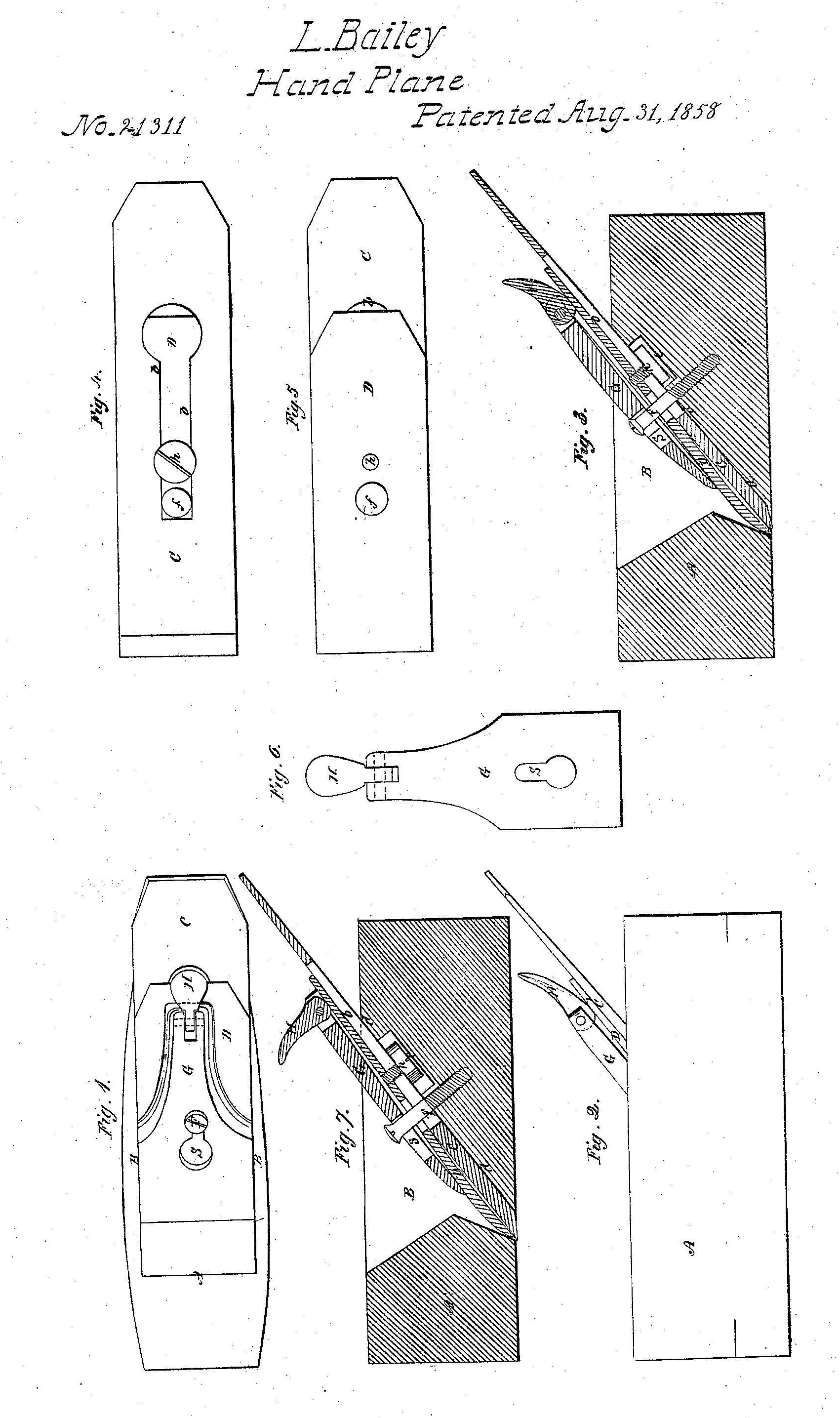
| To all whom it may concern: Be it known that I, LEONARD BAILEY, of Wilichester, in the county of Middlesex and State of Massachusetts, have invented a new 5 and useful Improvement in Hand-Planes; and I do hereby declare that the same is fully described and represented in the following specification and the accompanying drawings, of which Figure I denotes a top view of a smoothing plane having my invention applied to it; Fig. 2, a side elevation of it, while Fig. 3 is a central, vertical and longitudinal section of it. Fig. 4 is an underside view of the 15 plane iron and its cap, Fig. 5 being a top view of the same. Fig. 6 is a view of the clamp lever and thumb cam thereof to be hereinafter described. The object of my invention is to provide 20 the plane with a ready means of fixing the plane iron or cutter in the stock or of removing the same therefrom as well as of adjusting the plane iron in the stock as circumstances may require. 25 In the drawings, A, exhibits the plane stock furnished with a throat, B, for the reception of the cutter or plane-iron, C, or the same and its cap iron, D. In the above mentioned drawings the cap iron, D, is exhibited as confined to the plane iron or cutter, G, by means of a screw A, extending upward from the underside of the cutter G, and through a long slot, &, formed in the said cutter as shown in Figs. 3 and 4. The 35 bearing surface of the throat or that marked d, d, in Fig. 3, is furnished with a recess, e, for the reception of the head of the screw, h, by which the cap iron is confined to the plane iron, such recess being made of a sufficient size or diameter to allow the necessary longitudinal movements of the plane iron. Furthermore, the cap-iron as shown in the drawing, is made with a hole, /, arranged midway between its two edges and directly over the slot in the plane iron, such hole being to enable the plane iron and its cap to be passed over the head of a bearer • or screw F, inserted in the plane stock and made to project from the bearing surface cl, cl, as shown in Fig. 3. In connection with this screw or bearer, F, a clamp lever or plate, G-, is employed, it being formed as represented in the drawings and hinged or jointed at its upper end to a thumb cam, H. Moreover, the clamp lever, G, has an elongated slot, s, made through it, the said slot |
in one half its length being circular in form and having a diameter or width somewhat larger than the head of the bearer or screw, F, while the remainder of the slot is constriicted of a width or diameter less than that of the head of the screw and sufficient to receive the shank of the screw the whole being as shown in the drawings. In consequence of the slot being so made we are enabled to slip or pass the clamp lever, Gr, over the head of the screw and to press the said clamp lever, (r, downward in such manner as to cause the head of the bearer or screw to project beyond the sides of the slot, and constitute a fulcrum for the clamp plate when the thumb cam is turned down into the position as shown in Figs. I and 2. By turning the thumb cam down, we clamp or confine the plane iron in the stock, but by turning such thumb cam upward so as to bring it into the position as represented in Fig. 7 (which is another longitudinal sec- tion of the plane) we loosen the clamp lever from the bearer in such manner as to enable us either to remove it therefrom or to adjust the plane iron as circumstances may require. By turning backward the thumb cam, it will be made to so operate against the plane iron or the cap thereon as to raise the upper end of the clamp lever and force the lower end against the bearer in such manner as to cause the lower end of the clamp plate to be pressed downward upon the pla-ne iron and secure such iron firmly upon its bearing surface, d, d. Thus it will be seen that by means of the bearer, the clamp lever and the thumb cam the plane iron may be se- cured in place in the throat of the plane stock or released therefrom with great facility or expedition. By making the shank of the bearer to screw into the stock we cause the bearer to be adjustable with reference to the seat of the plane iron, and therefore we have a means of readily adapting the bearer to a plane iron of any ordinary thickness, whether provided or not with a cap iron, the adjustment of the bearer being for the pur- pose of causing the thumb cam and the clamp lever to be brought into the proper situations to enable them by their conjoint action as described to fasten the plane iron to the stock. If desirable, there may be two bearers, F, but I prefer to have but one, as BaO such is quite sufficient. These bearers may be arranged near the edges and may project | |
| either from or into the stock. A single bearer, however,
arranged in the middle of the seat of the plane iron and either made stationary or
adjustable with respect to 5 such seat is far preferable to more than one. Furthermore by
the employment of one bearer and its arrangement at the middle of the plane iron and the
clamp lever as described the lower bearing edge of the clamp 10 lever is left free to
perfectly or so perfectly adjust itself to the plane iron or the cap iron thereof as to bear thereon throughout the entire length of the edge. |
I claim.— The application and arrangement of one or more bearers, F, the clamp lever, Gr, and the thumb cam, H, together and with respect to the top surface of the plane iron and the bearing surface or cutter seat, d, cl, of the throat substantially as represented and described. .
LEONARD BAILEY. |
|