Goto USPTO Information Page for this patent
Justus A.Traut's 10/21/1884 (improved lateral)
306,877
UNITED STATES PATENT OFFICEo |
||
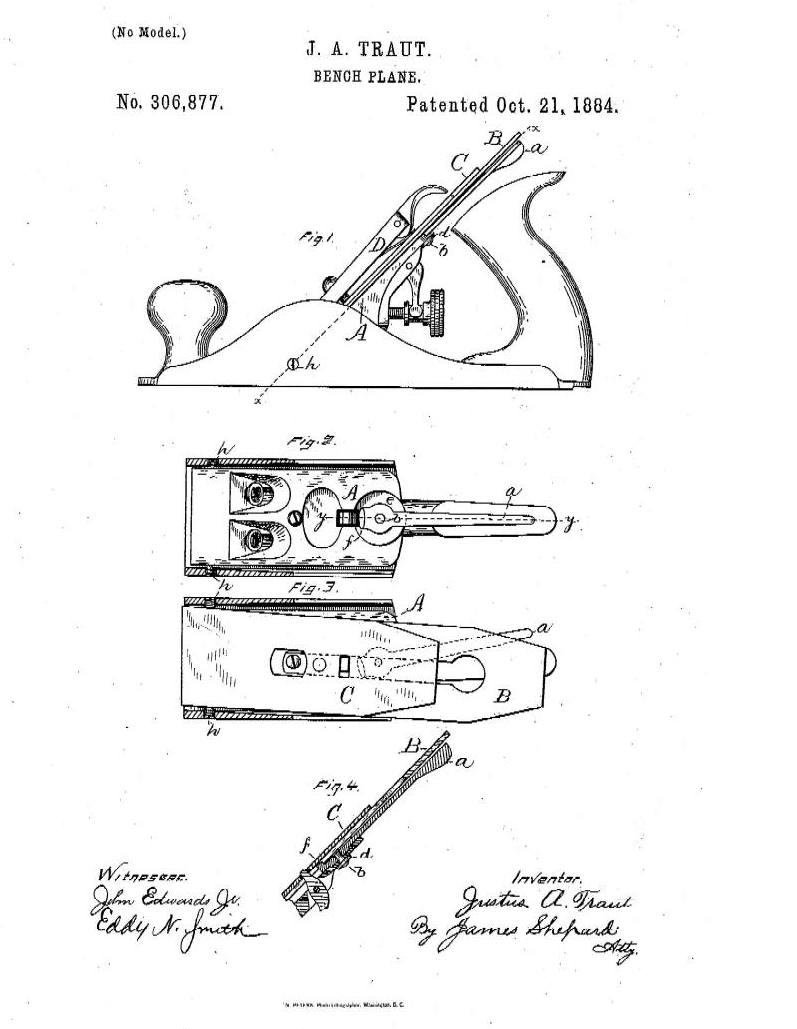
| To all whom it may concern: Be it known that I, JUSTUS A. TRAUT. a citizen of the United States, residing at New Britain, in the county of Hartford and State g of Connecticut, have invented a new and use- ful Iniprovt-nient in Bench-Planes, of which the following is a specification. My invention relates toiniprovemeuts in bench-planes, and the ohjer't of n)y invention io is to produce a better niechanism for ndjnsfr- ing the cutting-edge of the hit to square it. with the stock. I attain this object by tlie simple construction illustrated in tlie accom- panying drawings, in whif'.li— 15 Figure I is a side elevation of my improved bench-plane. Fig. 2 is a sectional viewtliere- of, partly in elevation, on line a; a" of Fig. 1. Fig. 3 is a like view with cutter attached, and Fig. 4 is a sectional view thereof online ?/ y 20 ofFig.2. • It is oftentimes difficult to grind the cut- ting-edge of a plane-hit exactly square, and- therefore when set in place it does not stand square witli the Stock. Several prior patents 25 s'iow planes having mechanism fur effecting this lateral ndjnstmeiitof the cutting-bit edge- wise. one of which mechanisms is a lever ar- ranged under the bit at the upper end of the li'og. Another consists of two screws the heads 30 of which act upon the edges of the bit at tlie upper end of tlie frog. Anotherpatentsliows side screws near the iniddle of the stock. which, in connection with swinging' dogs and a sliding piece, hold tlie bit in its adjusted 35 position. All of said prior art is hereby dis- claimed. The major portion of my plane is the same as ordinary bench-planes. The par- ticular plane illustrated is the one known as ': ailey's patent plane." 40 I secure the edgewise-adjusting, lever a to the plane seat or frog by means of the rivet b and waslier d, said washer producing suffi- cient friction to keep the lever a in place when the cap is removed. This lever is also qj let into the frog or hit seat A, so as to bring its upper side just below the under side of the bit B, as shown in Figs. I and 4, and said frog or seat is aJso cut away, as at e, Fig. 2, in order to permit a lateral movement of the 50 lever a. The lower end of said lever is pro- vided with a projection, /, which, rises above the surface of the frog or seat A a distance about equal to the thickness of the bit B, but not far enough to bind against the under siir- 55 ~ce of the cap-iron C. This projection/is |
of a width which will about fill the ordinary slot for the cap-screw at the upper end of the bit. I prefer to provide the under side of tlie lever a with a small boss or trunnion con- centric with the rivet b, on which it is ful- 60 ('ruined, and sink said trunnion into a circu- lar recess, as shown in Fi~. 4; but this con- struction is not essential. I also provide the stock with stationary pins h 1i near the lower end of tlie hit B. upon which said bit can 65 swingorfiilcrmii wlieniiiovt'dedgewisc. These pins lire threaded merely for convenience of insertion; hut when once inserted plain pins will answer the same purpose. When the parts are in place ready for use, 70 in order to adjust tlie bit edgewise to bring its edge square with tlie stock, it is only necessary to move tlie lever a to one side, as sliown in Fig. 3, which illustrates a bit whose end is ground out ofsiinare to an unusual de- 75 gree. It ehonid be observed that the lever a is close up under the bit, and does not so project as to ever render any inconvenience wliatever in the ordinary uses of the plane. I have shown this lever as the best-known 80 mechanism for an edgewise adjustment of the hit; but other mechanism for this adjustment located at the upper end instead of the lower I end of the stock will secure the advantages of I my invention. 85 Tliestationarypilisarelocated in thestock, [ so as to bear directly upon the edges of the bit near its cutting end, and. as the laterally- -adjnsting mechanism is operated to move the upper end of the bit edgewise, it will rock 90 or fulcrum upon thestationary pins at the low- er end. My mechanism for this edgewise adjust- ment does not in the least interfere with. the ordinary endwise adjustment of the bit, and c)i requires no change whatever in the ordinary parts of the plane, except to recess and drill the frog or bit and the stock for the reception and attachment of the lever a and pins A h. I claim as my invention— . ioo The combination of a plane stock and bit, an edgewise-adjusting mechanism for acting upon the bit at its upper end, and the sta- tionary fulcrani-pins h h in the Stock near the cutting end of the bit, substantially as de- 135 scribed, and for the purpose specified. JUSTUS A. TEAUT. Witnesses: JAMBS SHEPAED, 151)1~ N, SMTTH. | |