Goto USPTO Information Page for this patent
Edmund A. Schade's 9/3/1895 (fine frog adjustment)
545,732
UNITED STATES PATENT OFFICE
|
||
| To all whom it may concern: Be it known
that I, EDMUND A. SCHADE, a citizen of the United States, residing at New Britain, in the
county of Hartford and State of Connecticut, have invented certain new and useful
Improvements in Planes, of which the following is a specification. |
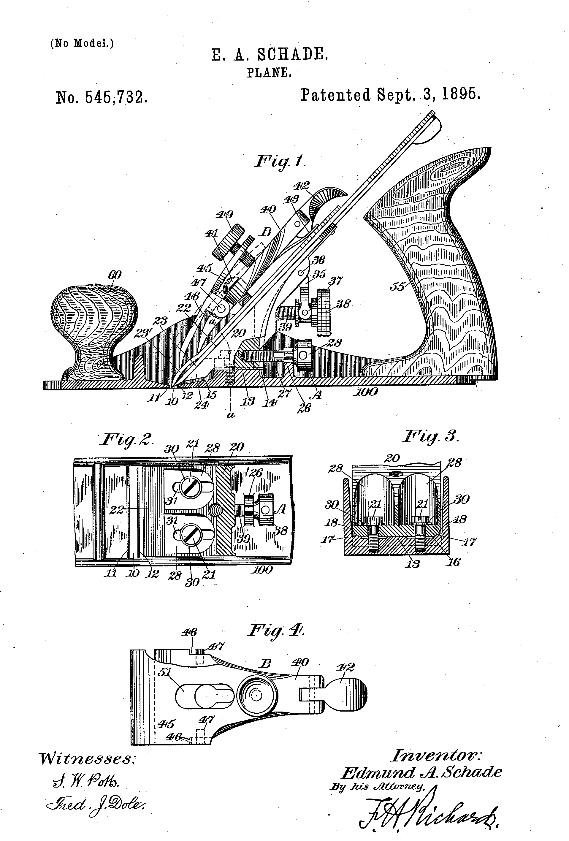
and is preferably integrally connected with said stock and extends transversely entirely across the stock, being united with the mouth of the plane by means of an inclined portion 15. This carrier seat or support 13 is somewhat thicker in cross-section than the sole of the stock to adapt it to re- ceive the locking devices of the plane-iron or 6o knife-carrier hereinafter described. .Instead of the seat or support 13 extending entirely across the stock, the knife-carrier seat or support may, if desired, consist of a pairof longitudinal shoulders on a plane parallel with the sole of the stock and extending inwardly a short distance from the sides of the plane. In this case, however, an intermediate hori- zontal support must be provided to receive the locking devices of the knife-carrier, hereinafter described. .When the seat or support 13 is constructed of a solid member extending entirely across the stock, as is the preferable construction, said carrier support or seat has a recess 16 therein forming two parallel longitudinal guideways 17, Fig.3. A knife or plane-iron carrier or bracket 20 is adjustably supported on the carrier seat or support by means of binding-screws 21, herein- after described, and is adapted to slide in} o the guideways 17, and has a recess 18 in its under side to engage the guideways 17 of the carrier support or seat. This carrier-bracket is shown as having a vertically-inclined side 22 relative to the sole of the stock, adapted to receive the plane iron or knife 23, and is provided at its under side .with a horizontal bearing-face parallel with the face 14 of the support ,13, and. is adapted to slide on said carrier support or .seat. The carrier is extended below its horizontal face 14 to form a support 24 for the lower end of the knife, and is preferably.V-shaped, to permit the under edge thereof to be inclined parallel with the inclined portion 15, connecting the mouth of the stock and the carrier seat or support. A suitable ad justing device for the plane-iron carrier-bracket, designated in a general .way by A, is provided for adjusting said carrier-bracket and thereby the knife relative to the in mouth of the stock, and is shown comprising suitable bracket-arm 26, preferably integrally connected to the stock of the plane, and in the upper end of which a threaded spindle | |
| 27, provided with a suitable thumb-nut 28, is.journaled, the
screw end thereof worliing in a suitable screw-threaded recess in the rear side of the
carrier. By turning said thumb-nut the carrier-bracket will be adjusted to the desired
position by sliding upon its horizontal support or seat toward or from the mouth of the
stock. In order to adjustably secure or clamp the io carrier-bracket upon its seat or support 13, binding-screws 21 are preferably used and are passed through elongated slots 31 in that portion of the carrier which has its upper face in aplane parallel with the lower or seat-engaging face of the carrier-support, in order that the carrier may be moved relatively to its seat or support without effecting the positioning of the binding-screws, and to permit this the carrier is shown as having recesses 28 countersunk therein and communicating with the inclined face 22 of said carrier. Washers 30 are disposed between the heads of the bind- ing-screws and the horizontal upper face of the carrier-bracket, and said carrier-bracket, by means of the elongated slots 31, can be adjusted in longitudinal direction of the stock by means of the adjusting device A, herein- before described. By this particular construction and organization of the plane-iron or knife-supporting members of the plane iron or knife a perfect adjustment of the plane is obtained, and, moreover, a perfectly rigid support for the plane-iron or knife-carrier bracket is provided. Any suitable means for vertically adjusting the plane-iron may be used, but is shown as comprising a lever 35, pivoted at 36 to the carrier, and having its upper end in engagement with the cap- plate 23' for actuating the same toward and 40 from the plane-month, and thereby moving the plane-iron in the same direction. This lever has the usual forked tailpiece 37 engaged by a peripheral groove in an adjusting- nut 38, which works longitndinally upon a 45 screw or threaded post 39, fixed to the carrier. As a means for clamping the plane-knife 23 and its usual cap-plate 23' in position, I have provided an improved clamping device, designated in a general way by B, and which go comprises a main clamping-lever having a supplemental clamping-lever connected therewith, and thereby forming a double clamping-lever, which, in the preferred form thereof, is shown consisting of a main clamping-lever 40, working on a fulcrum-screw 41, disposed on the carrier-bracket and having pivoted to its upper end the usual actuating cam-lever 42, having its cam-face 43 in operative engagement with the upper face of the cap-plate. Pivotally connected to the main clamping- lever 40, at any suitable place thereon, and projecting beyond the lower clamping end of said lever, is a supplemental clamping-lever 45 of any suitable construction adapted for the purpose herein set forth and of comparative flexibility relative to the main clamping- |
lever. The main clampiag-lever 40 has recesses 46, and is
provided with laterally-projecting pins or studs 47, upon which the 70 supplemental
clamping-lever is adapted to swing by means of suitable ears or Ings 48, having apertures
therein adapted to engage said pins or studs. As a means for adjusting this supplemental
lever, the upper end thereof is provided with a suitable adjusting device, herein shown as
a set-screw 49, adapted to work on the upper surface of the main clamping-lever. This
supplemental clamping-lever also has an 'elongated aperture 51 to permit 80 the
fulcrum-stnd 41 to be adjusted into position. By means of this improved clamping device,
one lever of which is adapted to engage the cap-plate at a point beyond the Clamping end
of the other lever, the knife Sc, or plane-iron is firmly held at different points near
its working end, and vibration thereof in the use of the plane is substantially elimi-
nated. Having thus described my invention, what I claim is— 1. In a piano, the combination with a. stock, and with a plane-iron supported thereon; of a clamping device for the plane-iron compising two clamps, one of said clamps clamping 05 the plane-iron at a point in advance of the clamping-point of the other clamp, substantially as described. 2. In a plane, the combination with a stock, and with a plane-iron supported thereon; of ioo a clamping device for the plane-iron comprising two clamps, one of said clamps clamping the plane-iron at a point in advance of the clamping-point of the other clamp; and means for separately operating the clamps, substantially as described. 3. In a plane, the combination with a stock; of a carrier-bracket supported thereon; a plane-iron adjustably supported on said bracket; a cap-plate adapted to rest on said no plane-iron; and clamping means for said plane-iron comprising a main clamping-lever fulcrumed on the carrier-bracket and a supplemental clamping-lever pivotally adjustable on said clamping-lever and adapted to iig clamp the cap-plate at a point beyond the clamping-point of the main-lever, substantially as described. 4. In a plane, the combination with a stock; of a plane-iron adjustably supported on said 120 stock; and clamping means for said plane- iron comprising a main clamping-lever fulcrumed on the stock, and a supplemental clamping-lever pivotally adjustable on said main clainping-lever, and adapted to clamp izg the plane-iron at a point beyond the clamping-point of the main-lever, substantially as described. 5. In a plane, the combination with a stock; of a plane-iron adjustably supported on said 130 stock; a cap-plate adapted to rest on said plane-iron; and clamping means for said plane-iron comprising a double-lever fulcrumed to the stock, one of said levers clamp- |
| ing the cap-plate at a point beyond the clamp- ing-point of
the other lever, substantially as described. 6. la a plane, the combination with astock; g
of a plane-iron adjustably supported on said stock; a cap-plate adapted to rest on said
plane-iron; and clamping means for said plane-iron comprising a main clamping-lever
fulcrumed on the stock; and a supplemental io clamping-lever pivotally adjustable on said
main clamping-lever and adapted to clamp the cap-plate at a point beyond the clamping-
point of the main-lever, substantially as de- scribed. 15 7. In a plane, the combination
with astock; of a plane-iron adjustably supported on said stock; a cap-plate adapted to
rest on said plane-iron; and clamping means for said plane-iron comprising a double-lever,
the 20 main clamping lever thereof being fulcrumed to the stock and the supplemental
clamping- lever being pivotally adjustable on said main- lever; and means for adjusting
gaid double- lever, whereby the adjustable action of the 25 combined levers extends to the
clamping ends of both the main and supplemental clamping- levers, substantially as
described. 8. In a plane, the combination with a stock; of a plane-iron adj ustably
supported on said 30 stock; a cap-plate adapted to rest on said plane-iron; a main
clamping-leverfulcrumed on said stock; means for adjusting said lever; a supplemental
clamping-lever pivotally ad- justable on said main-lever and adapted to 35 clamp the
cap-plate at a point beyond the clamping-point of the main clamping-lever; and means for
adjusting said supplemental- lever relative to the main-lever and inde- pendently thereof,
substantially as described. 9. In a plane, the combination with the 4 n J v • J.LJ. L« JJJ.L«LI~/) CYV VV LLJ YILLLUVIVY I1IY11 <JLJ.\J stock having a transverse month; of a horizontal carrier-support disposed thereon; and a carrier-bracket having a bearins-face substantially |
parallel to the horizontal face of the support, and adapted
to slide on said support, 45 and also having a vertically-inclined side adapted to support
a plane-iron) said inclined side extending below the bearing-face of the horizontal
support to support the plane-iron- adjacent to the mouth of the stock; a plane- go iron
adjustably supported on said bracket; means for longitudinally actuating said car-
rier-bracket relatively to its support; means for adjusting the plane-iron on its inclined
support; a cap-plate resting on the plane- gg iron; and a clamping device for said
plane-iron comprising a main clamping-lever ful- crumed to the carrier-bracket; an
adjusting device for said main clamping-lever; a sup- plemental clamping-lever pivotally
adjustable on said main-lever, and adapted to clamp the cap-plate at a point beyond the
clamping- point of the main-lever; and means for ad- justing said supplemental-lever
independently of the main-lever, substantially as described. 10. In a plane-iron, the
combination with a stock; of a plane-iron adjustably supported on said stock; a cap-plate
adapted to rest on said plane-iron; a main clamping-lever fulcrumed on said stock and
adapted to clamp said cap-plate and plane-iron; an adjusting device for said main-lever; a
supplemental clamping-lever pivoted on the main-lever at , a point below the fulcrum-point
of said main-lever, and adapted to clamp the cap-plate and plane-iron at a point beyond
the clamping- point of the main clamping-lever; and an ad- justing device for said
supplemental-lever, whereby said supplemental clamping-lever is adjustable independently
of the main clamping-lever) substantially as described.
EDMUND A. SCHADE. |